
How I can configure AVEVA Plant Scada to read a Steam Heater that have driver modbus RTU over TCP? With modscan I can read all the address, but with Scada bad response...
Thanks
How I can configure AVEVA Plant Scada to read a Steam Heater that have driver modbus RTU over TCP? With modscan I can read all the address, but with Scada bad response...
Thanks
Hi Carles
To communicate with a device using AVEVA Plant SCADA (formerly Citect SCADA) via Modbus RTU over Ethernet (also known as Modbus RTU over TCP/IP), you need to use the built-in MODBUS driver. This driver supports RTU framing and can be configured for TCP transport, typically when connecting directly to a device that supports RTU over TCP or via a serial-to-Ethernet converter/gateway that tunnels RTU frames over a TCP connection (without the Modbus/TCP header).
Note: If the device actually uses standard Modbus/TCP (with MBAP header), use the MODNET driver instead. Based on your query specifying "Modbus RTU over Ethernet," the MODBUS driver is appropriate. Ensure the device or gateway listens on a TCP port (commonly 502, but confirm with device docs).
Configuration is done in Plant SCADA's Citect Studio (or equivalent editor) under the Communications section. Set up Boards, Ports, and I/O Devices as follows:
This setup encapsulates RTU frames over a TCP socket without additional headers. Refer to the Plant SCADA Driver Reference Help (accessible in Citect Studio) for MODBUS-specific params.
Hi Oliver,
I'va been testing without exit...
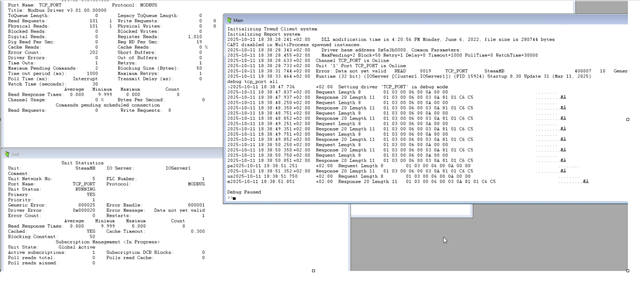
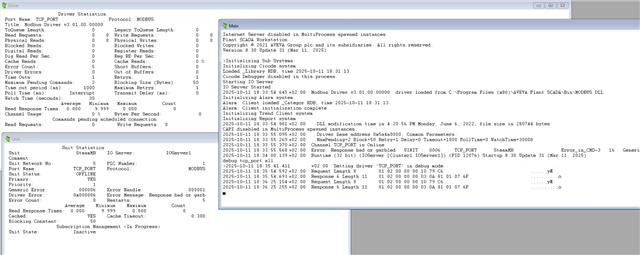
If I put DoCRC=0, goes online, but the next tag read fail....
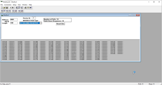
With modscan goes online and read all values (100 positions without problem)
The pictures are with DoCRC=1, and DoCRC = 0.
Any suggestion?
Thanks.
Hello Oliver,
Finally read the steam using Node-red. The modbus from Steam add at response TCP the CRC!!!, and driver MODNET says Data not valid...
There are some citect.ini option to use MODNET and CRC?
Carles
Hello Oliver,
Finally read the steam using Node-red. The modbus from Steam add at response TCP the CRC!!!, and driver MODNET says Data not valid...
There are some citect.ini option to use MODNET and CRC?
Carles
Hi Carles
There are no Citect.ini parameters or options to configure the MODNET driver to handle CRC (Cyclic Redundancy Check), as it's fundamentally designed for the Modbus/TCP protocol, which uses a different frame structure (MBAP header) and does not include CRC for error checking—relying instead on TCP's built-in mechanisms. Attempting to use MODNET with a device or gateway that's sending RTU-framed data (which includes CRC) will typically result in "Data not valid" errors or similar, because the driver parses the response expecting the Modbus/TCP format without CRC.
If your device is truly using Modbus RTU over Ethernet (e.g., RTU frames encapsulated in TCP without the Modbus/TCP header), stick with the MODBUS driver configuration as outlined in my previous response. That's the standard approach per AVEVA documentation and community discussions.
If you are still stuck and not able to find a solution, it might be worth exploring an alternative approach, such as gateway (PLC) to aggregate the data or another software that can communicate with the device and exposes an OPC layer for Plant SCADA to communicate with.
Kind regards
Olivier
Hi Oliver,
OK, thanks.
Now, we are doing a gateway in Node-Red, and reading it....
Kind Regards
Carles

